Dear developers, in my studio environment, I have a vertical screen and a ground screen. I tried the LUT calibration feature in Aximmetry and applied it to the Out-of-Virtual Extension, and it worked well. But there is a problem, I can't measure the LUT for the vertical screen and the ground screen at the same time, and the virtual realm is not allowed to apply the LUT for the vertical screen and the ground screen separately, is there any good way.
About the calibration of LUTs on multiple screens
Comments
duchenyang
-
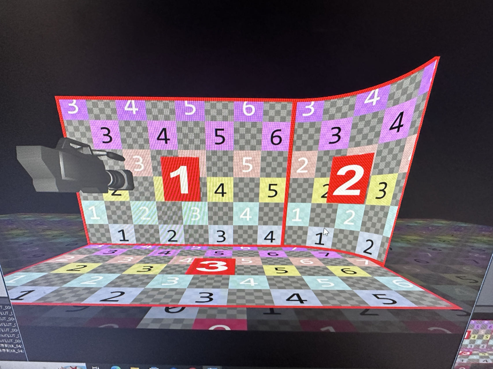
Hello developers, in the last project our screen configuration is as follows, I put the LUT area at the junction of the three screens, but the LUT from this has some strange chromatic aberration, is there a good way to calibrate the LUT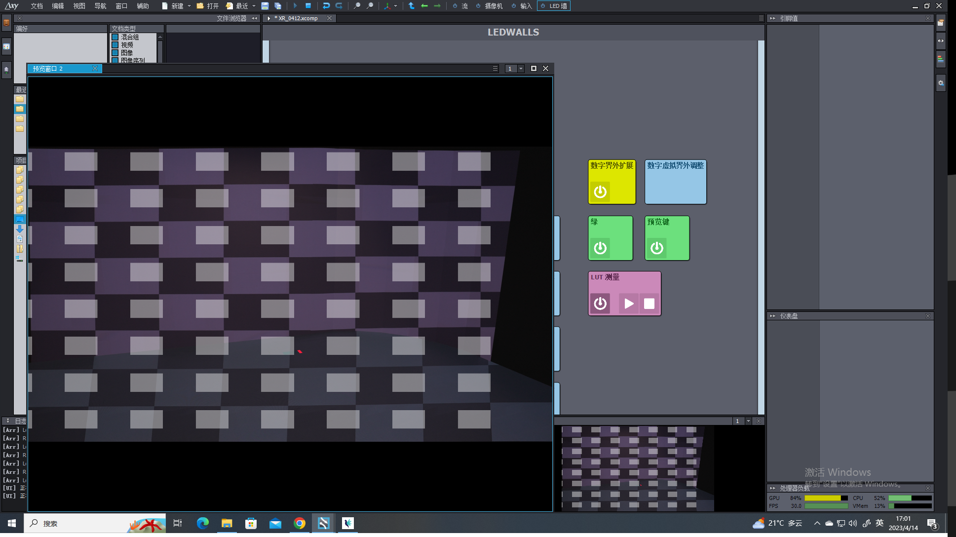
duchenyang
-
Another problem is that I am very uncomfortable aligning the junction of the curved screen and the straight screen, and I don't know if Aximmetry supports importing the external screen model, like UE's nDisplay function, which will make me get a correct curved screen. In addition, this step of screen alignment is also very headache, whether aximmetry supports screen alignment with Aruco code, which will make our alignment results very accurate, I see that UE official has this function, I don't know if I can implement it in aximmetry software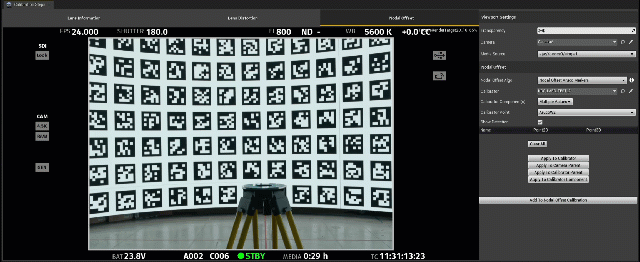
duchenyang
-
I noticed that there is such a module in the aximmetry software, can you please explain what the data of the transform pin generated by this module is, whether I can use this module to monitor the tracking data of the ARUC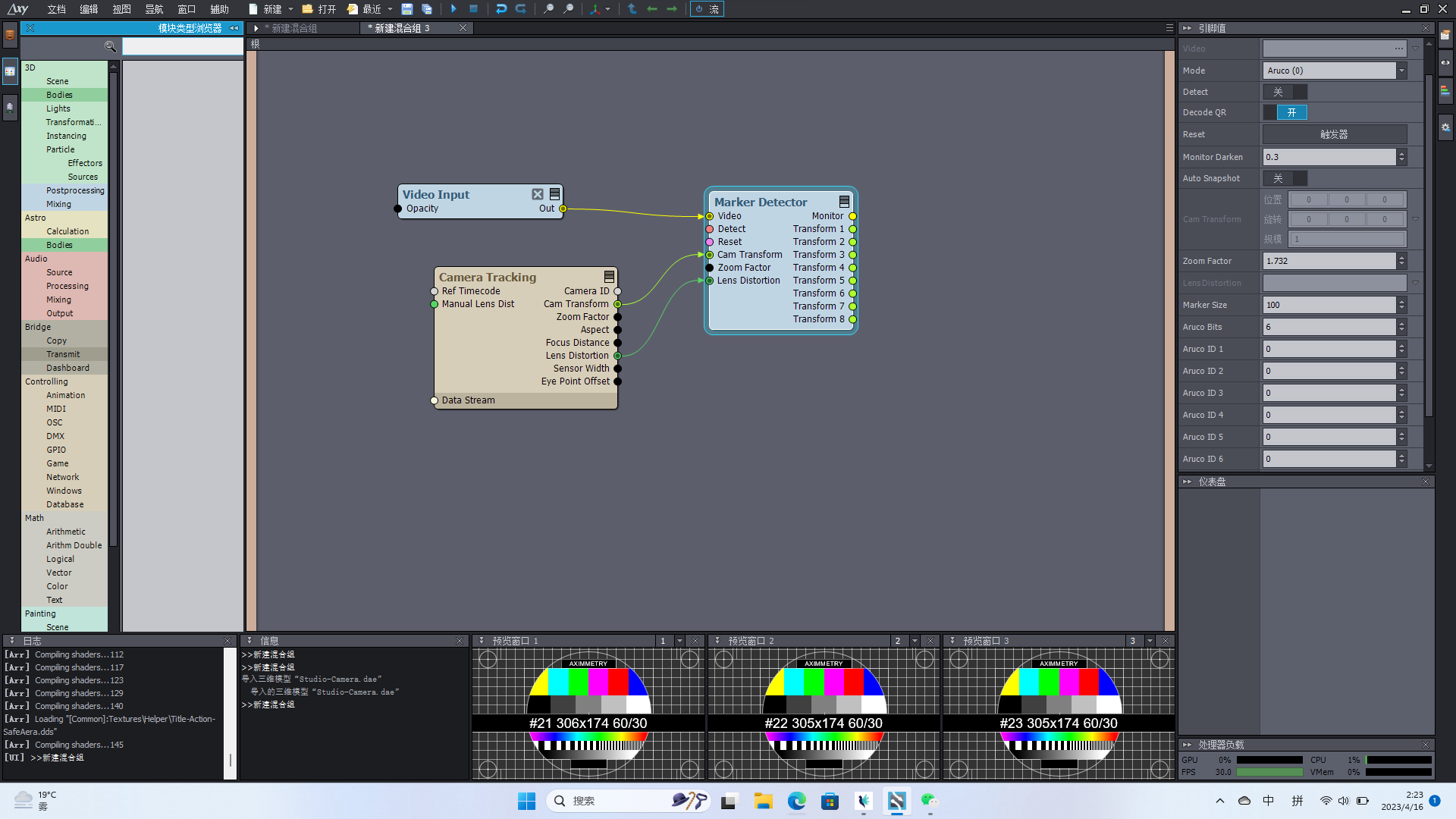 O code in real time when there is tracking data, so that it is feasible to use it as an alignment of the LED screen?
duchenyang
-
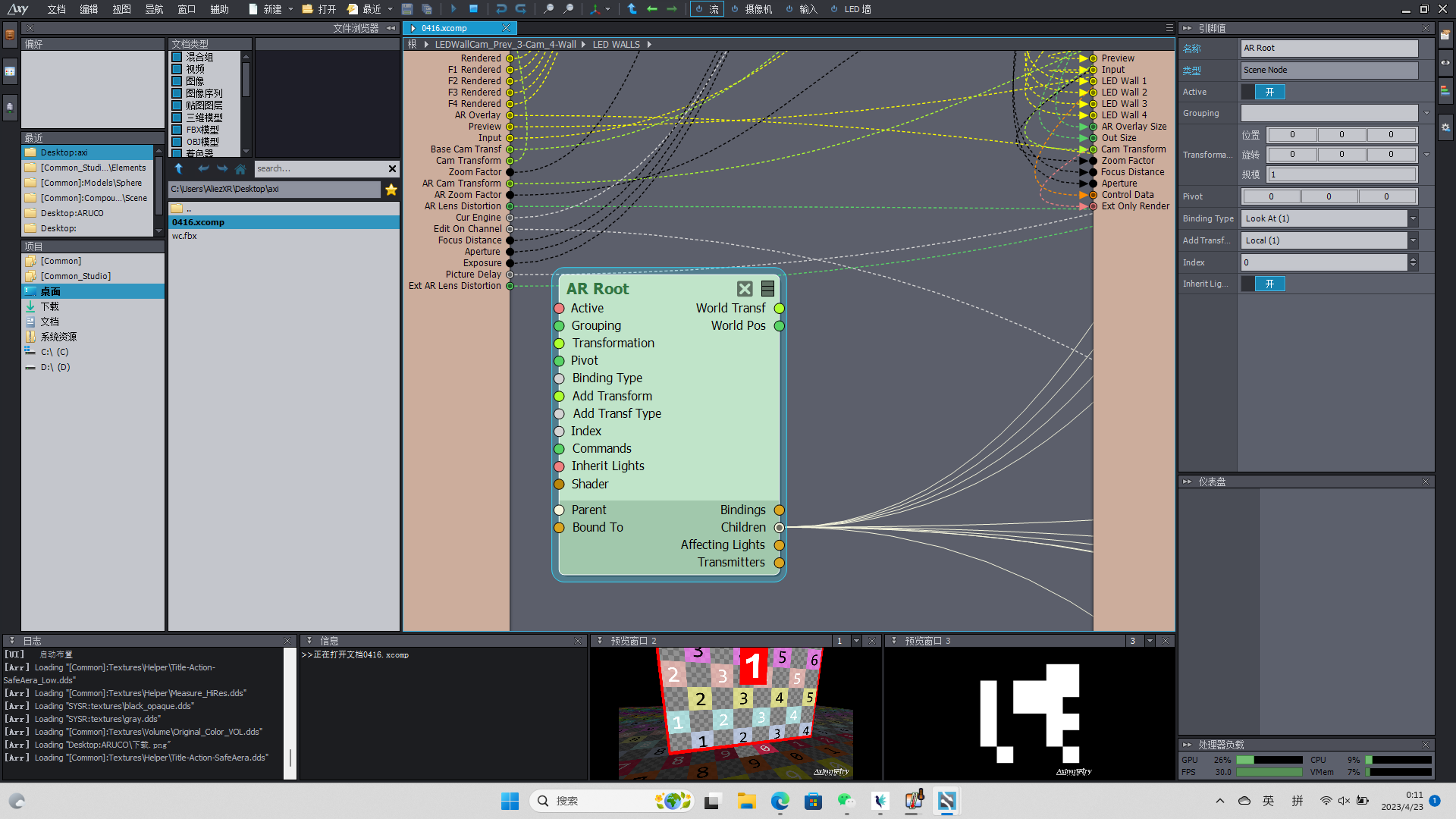
I noticed that there is a scene node called AR Root in the LED hybrid group, can I change it and replace it with the screen I want with Aruco graphics so that I can better calibrate the position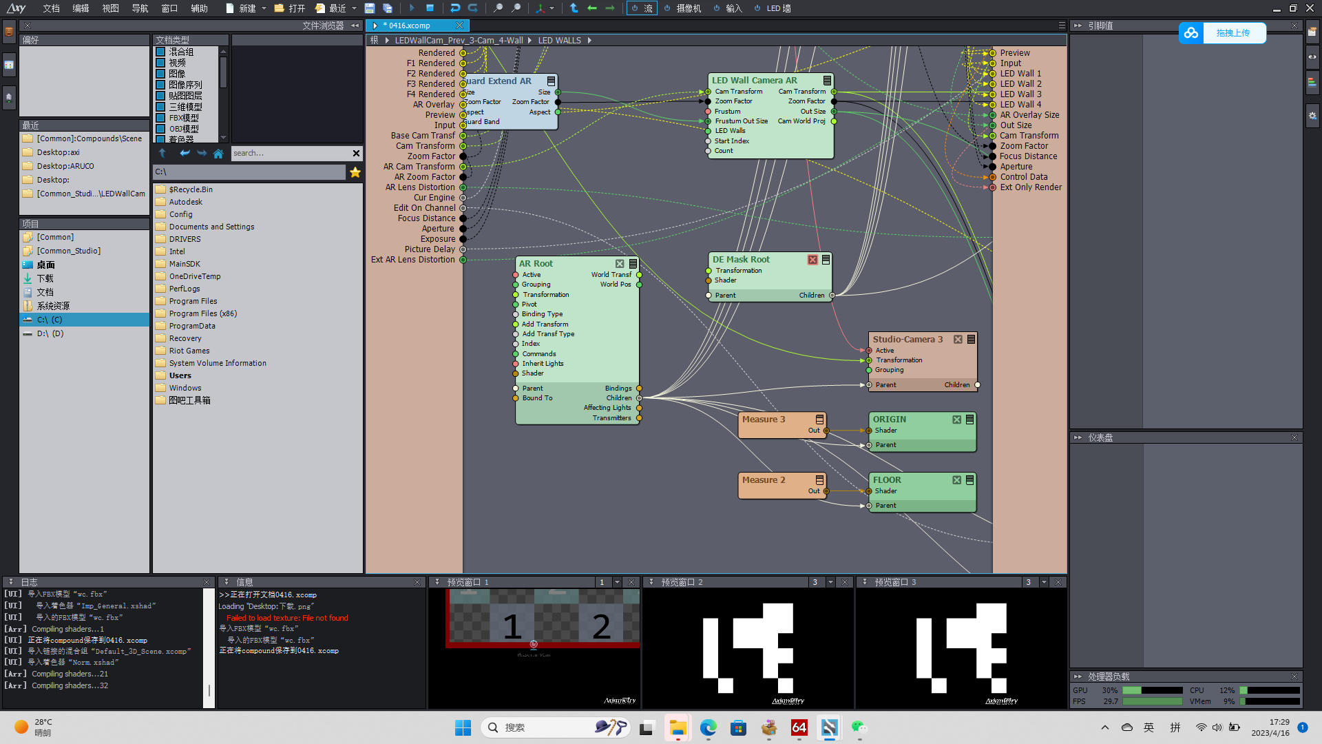
Eifert@Aximmetry
-
Hi,
Note, the virtual checker pattern should be inside the checker pattern of the LED wall, somewhat like the red rectangles here: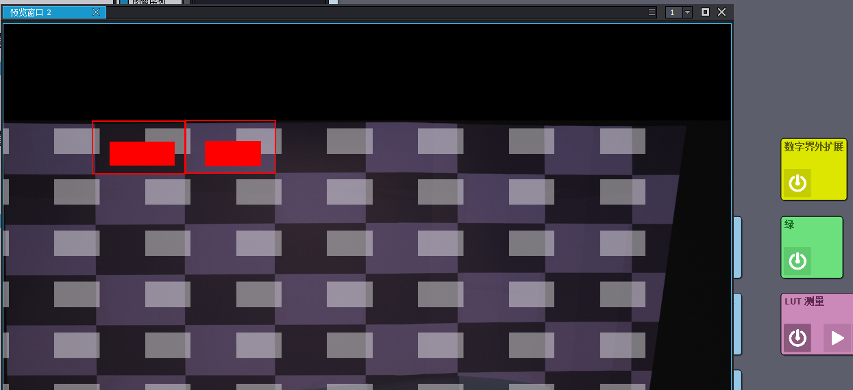
Otherwise, the calculation will be inaccurate!
You can offset the checker pattern here: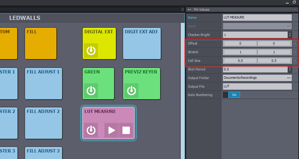
Also, there is no way to use an external screen model or LED wall position generated with ArUco. You were digging at the right place in Aximmetry, but in Unreal, Aximmetry uses a different system than UE's nDisplay, so you would have to make complex edits in Aximmetry's Unreal camera blueprint to make this work.
It would be much easier to just set the LED wall's position:
Using the ArUco detector and overwrite that pin in Aximmetry with the detected value. While you manually define the curve using the Radius setting.
You can find an image in my comment here: https://my.aximmetry.com/post/64-software-based-real-time-object-tracking of how to connect the Camera Tracking with the Marker Detector module.
Aximmetry has future plans to add a similar system to the one you want and to what you refer to here: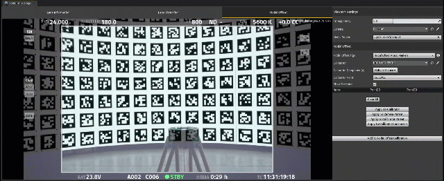
Warmest regards,
wangchen
-
Thank you for the previous answer, the idea you gave is completely correct, but I have a new problem, I have a way to change the picture output to the LED screen, but I did not send to change the appearance of the virtual screen when the LED preview, this seems to be a model? I FOUND THAT IT IS RELATED TO THE AR ROOT MODULE IN THE MIXED GROUP, IS THERE A WAY FOR ME TO CHANGE THIS MODEL OR IMAGE? I want to replace it with the ARUKO model or image I need so that I can better align the LED screen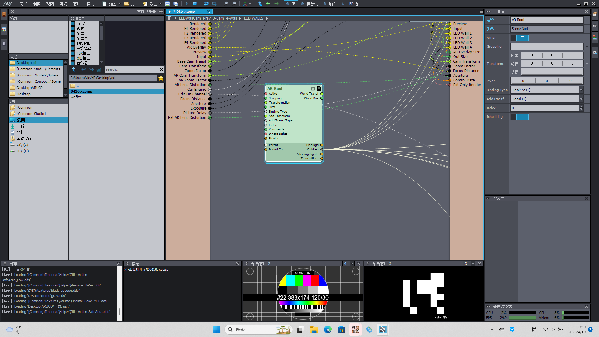
Eifert@Aximmetry
-
Hi,
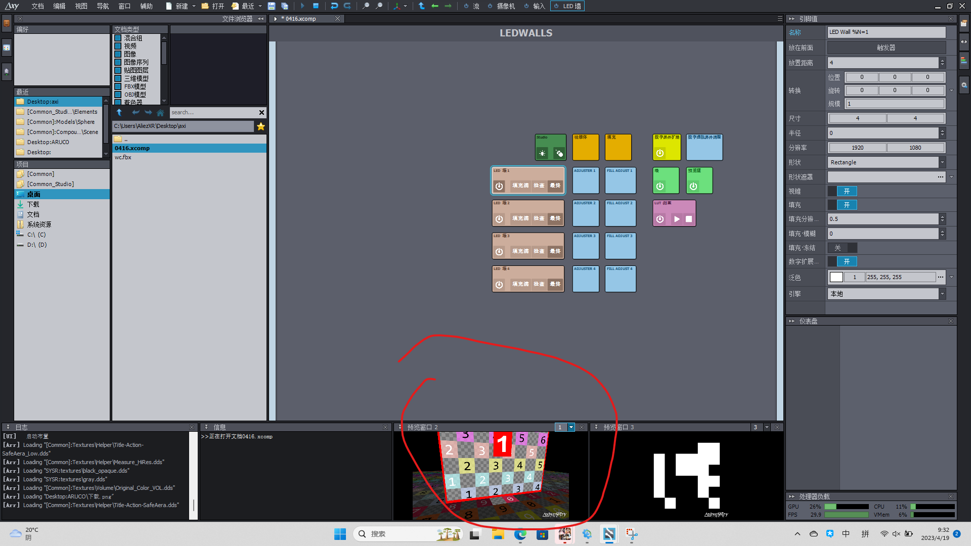
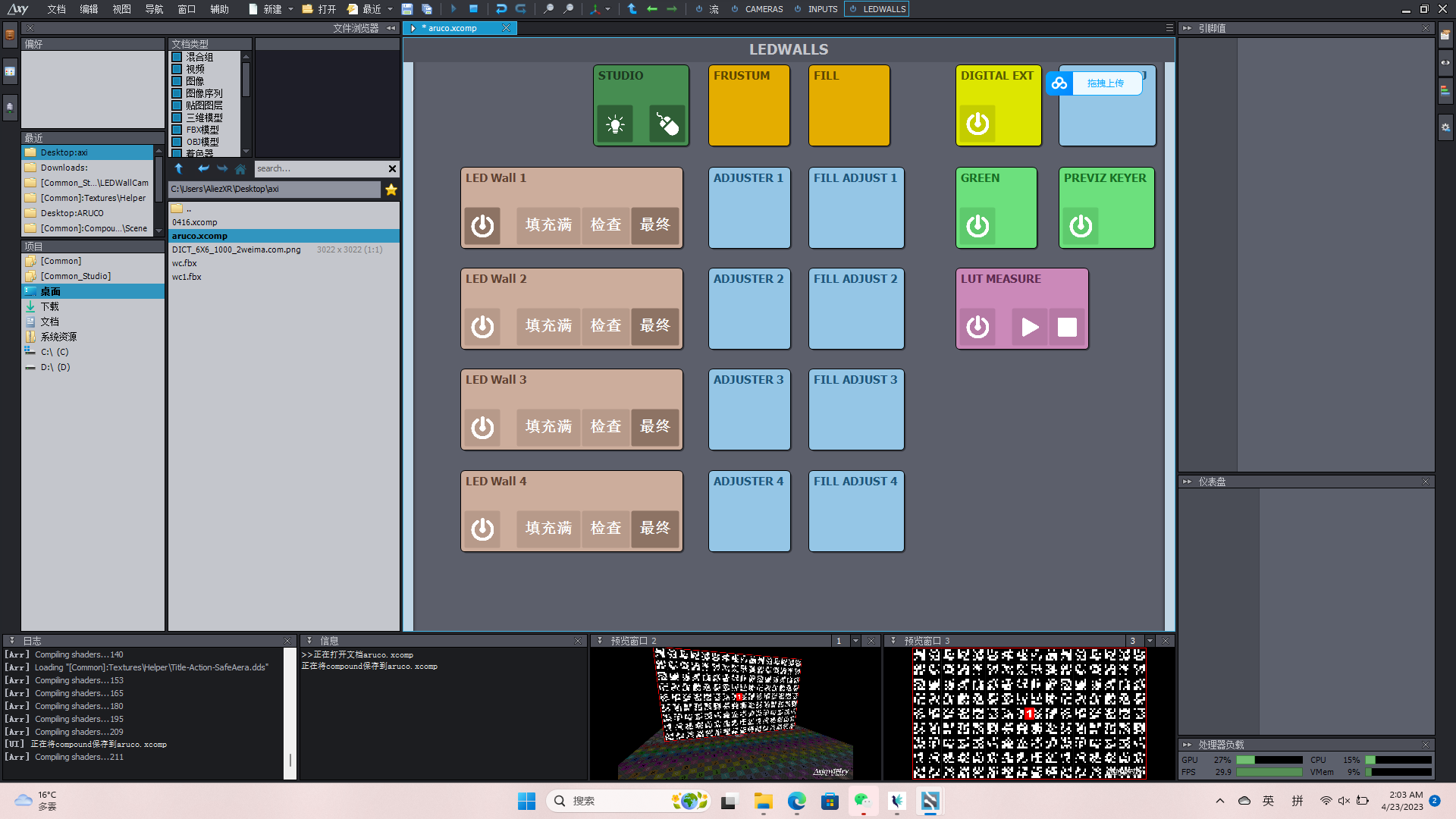
What you see there on the LED wall are the helper graphics which are turned on here: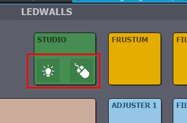
You can either turn them off.
Or follow their logic in the Flow Editor and change it for the LED Walls: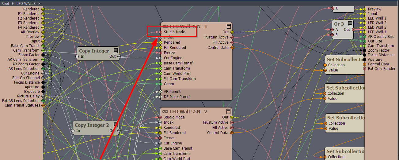
But this is not exactly what you will want, you will probably have to go into the above LED Wall %N=1 compound and change the helper graphics inside to an ArUco one, or multiple ones to get an average. You will also need to know after that what its relation to the real-world LED wall's size and calculate an exact transformation based on that.
It won't be easy, it will probably take much longer than a 1-day project... Also, you should consider that ArUco might not have the precision you want.
Warmest regards,
duchenyang
-
I have found that the LED auxiliary graphics are taken over by a module called AR root, what type of module is this module and how to modify and replace
duchenyang
-
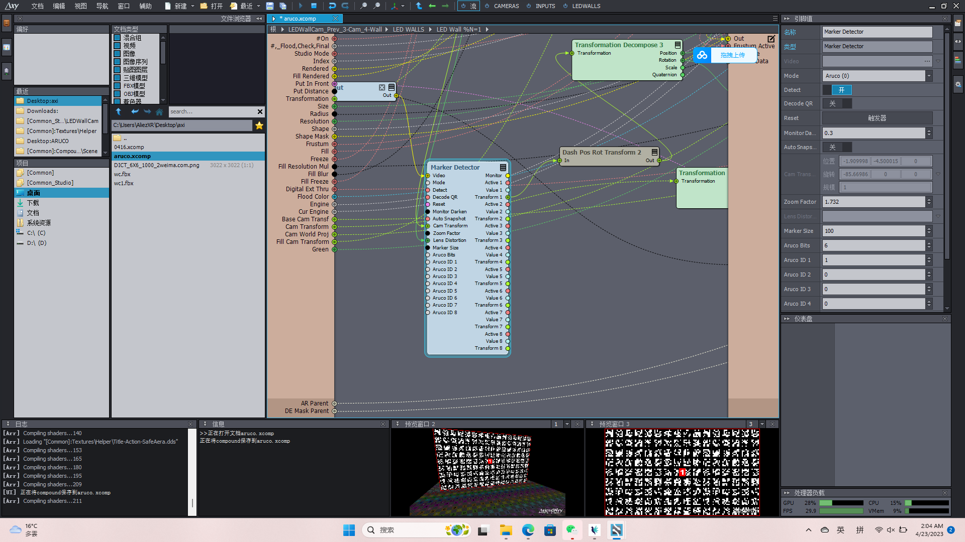
Dear developer, I have completed the modification of part of the LED module, now I can successfully map the Aruco graphics to my real LED wall and virtual LED wall, now the problem is that the marker detector that comes with Aximmetry is not very useful, it does not support the detection of multiple ARUKO, nor can it detect a range of IDs, is there any good way to modify this module or create a module yourself, I hope to get your answer
Eifert@Aximmetry
-
Hi,
You could use an Array Compound to detect more than 8 ArUco IDs: https://aximmetry.com/learn/virtual-production-workflow/preparation-of-the-production-environment-phase-i/scripting-in-aximmetry/flow-editor/compound/#array-compound
However, this will might need more processing power than 1 frame time. So you might want only to run this once or periodically using a Hold module after the Array Compound.
Also, I would suggest putting separator lines between the ArUco markers or having them separated like here with a white background and black outline: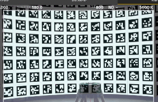
Otherwise, the Marker Detector module might have a hard time finding the markers.
Warmest regards,
duchenyang
-
I think you may not understand what I mean, the current marker module can only recognize after I give eight IDs, I want to modify it so that it can recognize the ARUKO code of multiple IDs under the same dictionary, because I can't determine the final ARUKO ID number projected on the screen when making the Arcuo map
Eifert@Aximmetry
-
Hi,
Ahh, I did misunderstand you. Sadly there is no such feature.
There are online ArUco generators that could generate for you the exact ids.
Also, in the case of QR, you can generate in Aximmetry: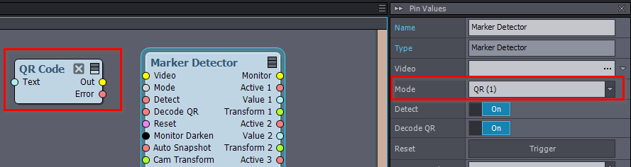
And QR's text is written out in the Value output pins.
And if the range of ID is small, you could still use an array compound to go through the range fast.
Note, if you expand the Marker Detector module, then there is an Active pin that tells if the marker is detected.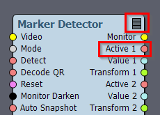
Warmest regards,
Eifert@Aximmetry
-
Hi,
We're excited to share that the latest version of
Aximmetry, version 2023.2.0, has been released today!
This latest update brings a new feature that automatically positions
your LED Wall in the correct location. You can trigger the automatic
positioning with Auto Place in the LED Walls: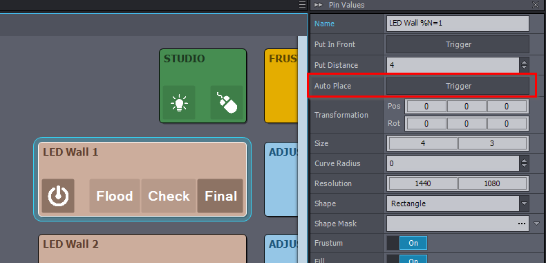
To learn more about all the changes and improvements included in this version of Aximmetry, please visit the following link: https://aximmetry.com/learn/software-version-history/
Warmest regards,
Hi,
You should measure only one LED wall screen's LUT. Most likely you want vertical to be the one measured as its colors will probably be less affected by your studio's environment compared to the ground one.
You should try to set the LED wall's (ground) Frustrum and Fill Adjusters to match its color with your LUT measured LED wall (vertical):
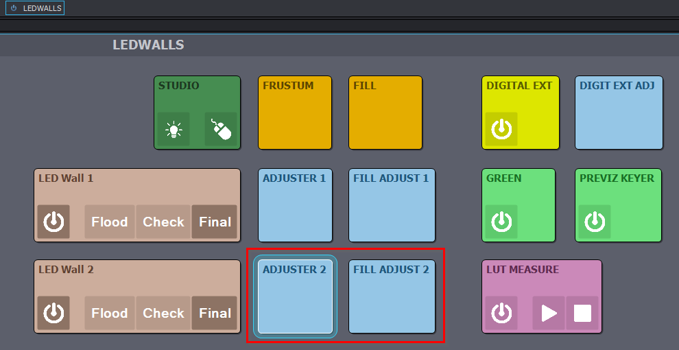
When doing so, you can compare the two LED walls even by looking at them in your studio, instead of through the camera. Since you only need to match the LED wall's output color.
Please also let us know if the Adjusters were enough to match the LED wall's color. If not, do you have the same type of LED walls for ground and vertical?
Warmest regards,