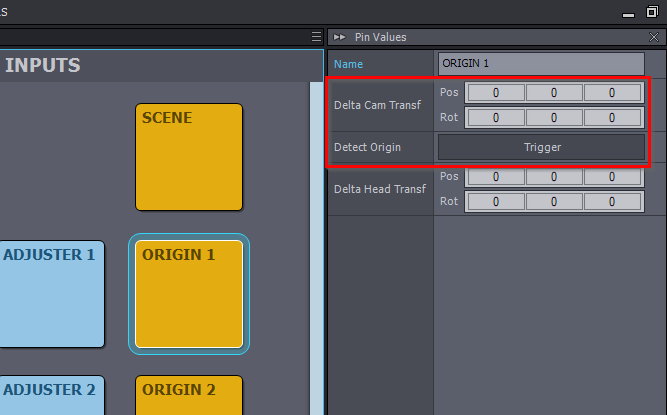
We tried the process recommended on the documentation to ensure that the position of the screen coincides with the virtual position by measuring the distance input into Aximmetry. However, there is no way to measure the value of the rotation above, so the LED and the external expansion screen cannot be fully connected. We also tried to use auto-calibration to make the LED screen and the virtual screen match each other. Either way, there's no way to align them perfectly. I wonder where we did it wrong?
I wonder how we should go about measuring the angle at which the screen rotates. Since we are using a camera crane, I would also like to know if the offset data of the camera crane arm will have an impact on the calibration of the screen. And is there a better way to do LED calibration?

Hi,
Before you set up the positions of LED walls in Aximmetry, you should make absolutely sure that your tracking is as accurate as it can be.

You should use the Camera Calibrator and once you are done with the calibration you should click on Test Calibration, then set the Tracking Delay, and check if the virtual floor stays at the same place as the real world's floor if you move your camera a lot:
Also, is your crane tracked? If not, then you won't be able to use it as a tracked camera.
If your LED wall is curved then you must make sure when you set it up that it is curved evenly. You will have to place curved LED walls in the virtual world manually as the auto-placement on curved LED Walls won't work accurately. When setting it up manually you should follow what is written here: https://aximmetry.com/learn/virtual-production-workflow/preparation-of-the-production-environment-phase-i/led-wall-production/using-led-walls-for-virtual-production/#specifying-the-led-wall-positions and measure the center of your curved LED wall for the position in the virtual world.
Warmest regards,