[Feature Request] Discrete XYZ Controls for start/end of a 3D Cylinder (or Plane Selector in PathExtrusion)


Hi Folks.

I'm trying to connect certain points on a map with straight lines.

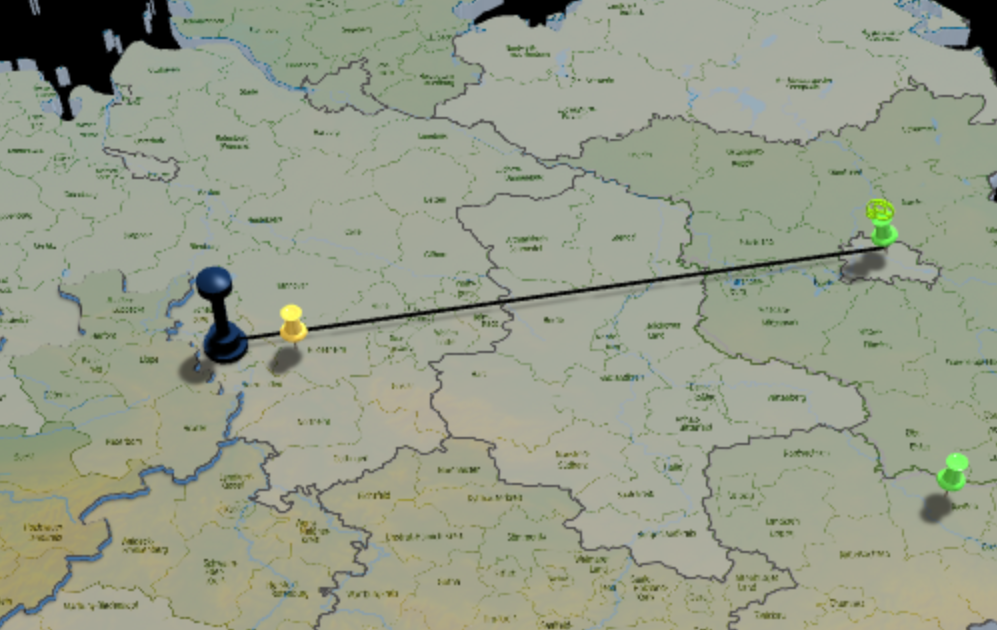
So e.g. the 'Black Tower' is connected to the green 'TackPin'.
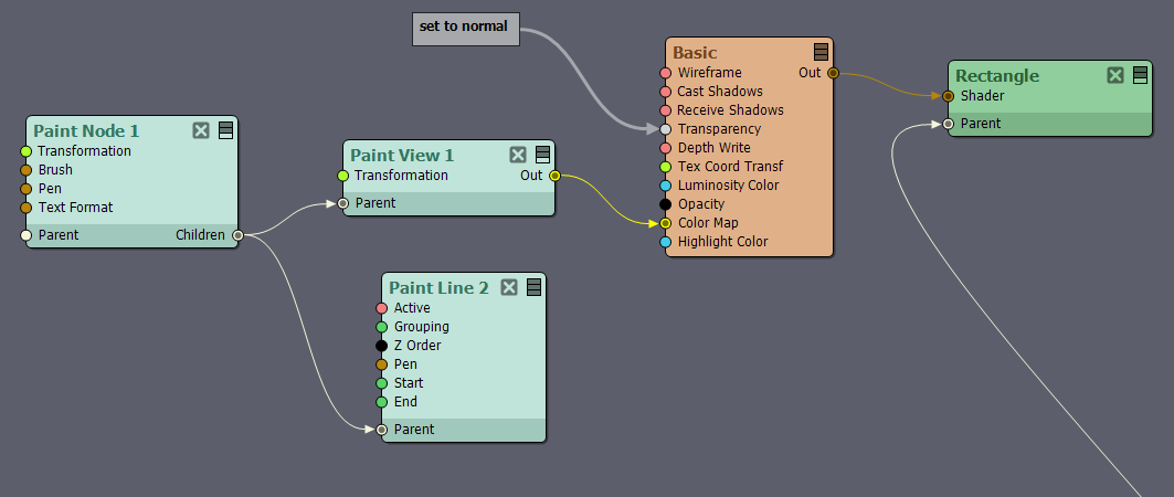
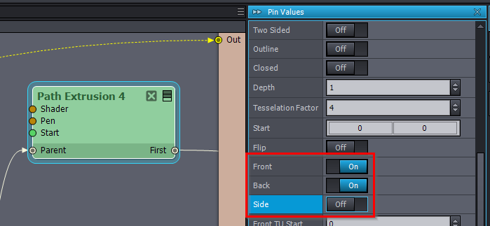
In this example I'm using a PathExtrude setup, since it sports those discrete Start/End parameters.
But opposed to the 3D Cylinder which has that 'Plane' value to determine in which 3d plane it lives,
that parameter is not available in PathExtrude.
Hence the line looks more like a 'wall' on the map.
Also I couldn't figure out how to have multiple lines in an Array to visually connect the BlackTower to all the TackPins.

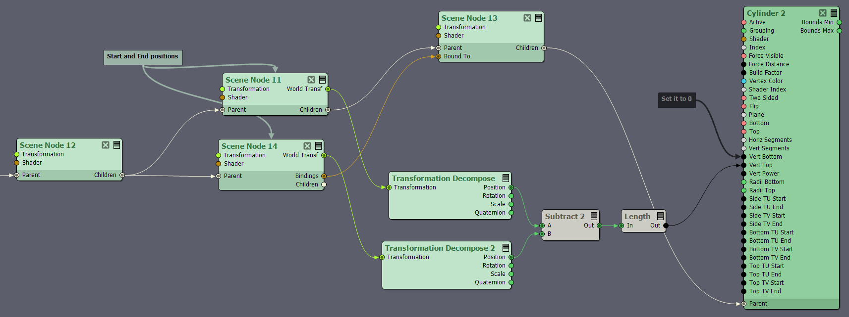
Ideally this would work with a cylinder, which could be easily put inside an Array to create a multitude of them.
But unfortunately the cylinder only has Top/Bottom Controls defining the height, rather than XYZ Coords for placing Top and Bottom at distinct locations in the scene.
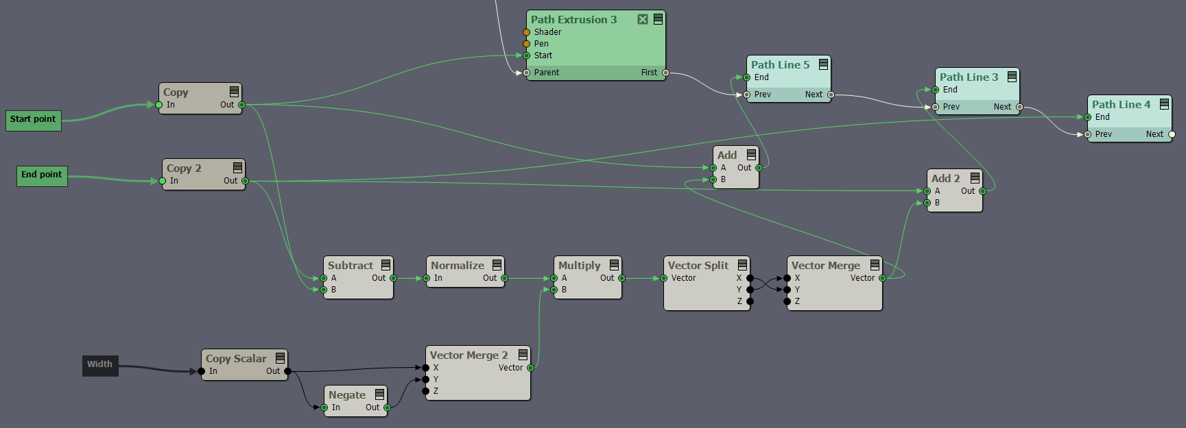
There's probably some weird vector math which would allow me to
- create that cylinder with a height equal to the distance between the BlackTower and the associated TackPin,
- align one end of the cylinder with the BlackTower and
- Figure out the rotational vector to point the cylinder into the direction of the TackPin.

But having XYZ Coords would make this soooo much easier :-)

Cheers & all the best.


Eric.


   EricWest

 
Profile Image
EricWest
  -  

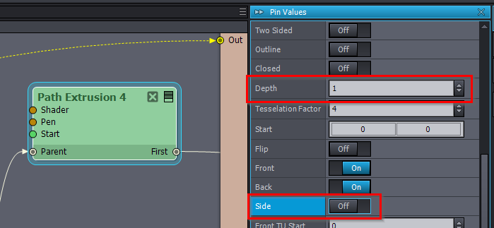
Correcting myself here, PathExtrusion actually *does* work nicely within an array.

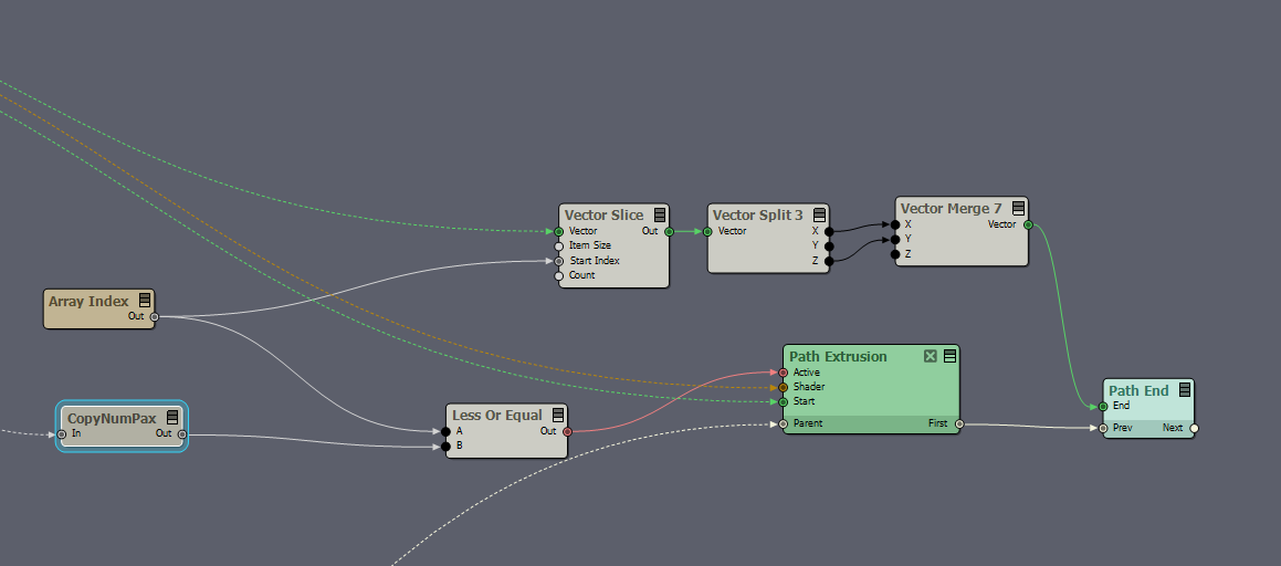
But there's still the issue of the lines living on the wrong plane, rendering some of them almost invisible:


So maybe I should make this more into a feature request of having a 'Plane selector' in PathExtrusion similar to the Cylinder :-)

 
Profile Image
Eifert@Aximmetry
  -  

Hi Eric,

Paint View
If you want the most creative control, then you could use the Paint View module and put the rendered image in front of your map in a transparent rectangle. In this case, the lines can be easily drawn using the Paint Line module:

This gives you lots of creative control, cause you can use your mouse for example to draw over the map. There are many other modules with other functionalities when using Paint View. You can find some examples in the tutorial package's Paint And Touch folder ([Tutorials]:Paint And Touch).


Cylinder
You can actually easily stretch the Cylinder between two points using the Look At Binding.
By default, Scene Node's
Binding Type pin is set at Look At, but it is not used by default cause nothing is connected to its Bound To pin.
You need to set up the following logic:
However, this will probably not look the best on a 2D map like in your picture.


Path Extrusion
The Path Extrusion was intended to be used like Text Extrusion, to draw shapes like you would draw the text with Text Extrusion. But you can still use it to draw paths on a map with some additional logic.

The Path Extrusion looks like a wall, cause it is a rectangle in your setup and mostly the edge is facing toward your camera.
You can change the width of the sides (wall height) with the Depth pin or turn it off with the Side pin:

You could create a front for it by adding 2 more Path Line modules to define a front-facing plane with 4 points. In the Path Extrusion module, this will represent the Front and Back sides of the Path, so you can even turn off the Side pin:

With the following additional logic, you can ensure that the Front has the same width no matter where the Start and the End points are:

Note, modules that can be used with the Path Extrusion can also be used with the Paint View's Paint Path module.

Warmest regards,

 
Profile Image
EricWest
  -  

Hi Eifert.

Another awesome deep reply. Thanks so much!
Especially the cylinder trick is amazing!

Cheers & all the best.


Eric.